In general, topology is the structure or physical arrangement of objects. In electrical networks, topology means the physical set-up of the network.
Network
Test points are combined to one network (Tp = test point):
C (Tp.1, Tp.2, Tp.3, Tp.4, Tp.5)
If a network consist of more than 2 test points, indeed these are electronically at the same potential, but physically they can be arranged differently.
Star
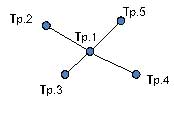
With individual commands the network is split in a star-shaped manner:
C (Tp.1, Tp.2); C (Tp.1, Tp.3); C (Tp.1, Tp.4); C (Tp.1, Tp.5);
Test step 1: connection between Tp.1 and Tp.2
Test step 2: connection between Tp.1 and Tp.3
Test step 3: connection between Tp.1 and Tp.4
Test step 4: connection between Tp.1 and Tp.5
see figure 1: Network in the form of a star
Chain
With individual commands the network is split in a chain-like manner:
C (Tp.1, Tp.2); C (Tp.2, Tp.3); C (Tp.3, Tp.4); C (Tp.4, Tp.5);
Test step 1: connection between Tp.1 and Tp.2
Test step 2: connection between Tp.2 and Tp.3
Test step 3: connection between Tp.3 and Tp.4
Test step 4: connection between Tp.4 and Tp.5
see figure 2: Network in the form of a chain
In case a detailed failure description from the test system is needed, it has to be ensured that in the development of the test program the UUT-corresponding topology is programmed in the editor.
It can be either by programming the connections according to the realities or by giving the tester the topology that needs to be verified (Mode(Star) or Mode(Chain)).

